


Hey people!
So a while ago I bought an old Vacuum Florescent Display tube, and attempted to build my own controller for it. Well I’ll keep that story brief but it doesn’t need saying that I failed dramatically, and blew about £60 on it ($96).
But I didn’t give up and a couple of weeks ago I bought myself an awesome little board from OSHPark. Built by a user named ‘Awesomenesser’. Unfortunately I have no means of contacting this person but I would sincerely like to thank him/her for making this awesome little board.

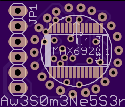
Built by Awesomenesser
The board itself uses a MAX6921AUI. Which is a VFD controller chip made by maxim integrated. This chip is absolutely awesome so if you are thinking of doing a VFD project really do check it out!
Unfortunately the board was supplied with no instructions so I sat down for a while and compared data-sheets until I had something that made sense. Now I don’t want you to have to do the same thing so I thought I’d do a little picture and you can see for yourself how it goes.
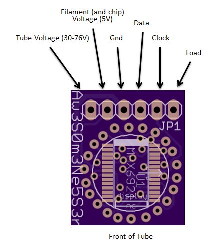
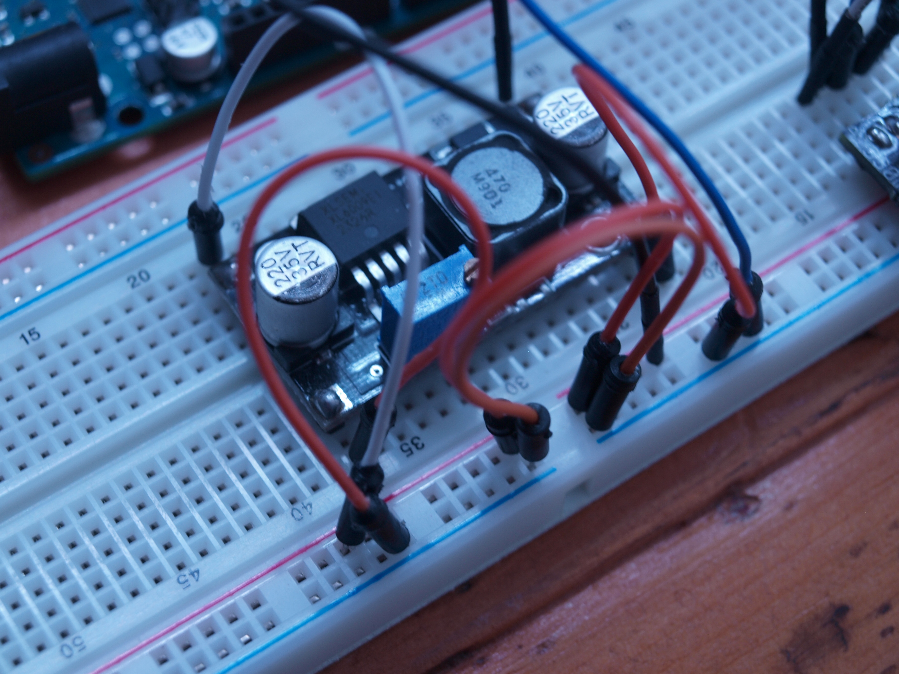
Some of you who know a thing about VFD tubes will know they run at high voltages, between 30 and 80 gives you a good bright light (though make sure not to exceed the 76V rating on the chip). So you may be wondering how I generated this. To do this I used the HCJ-IPM-V5 DC-DC step up converter, I would highly recommend this solution for anyone wanting up to 30V DC, simply because it is SO easy and simple and still very cheap.
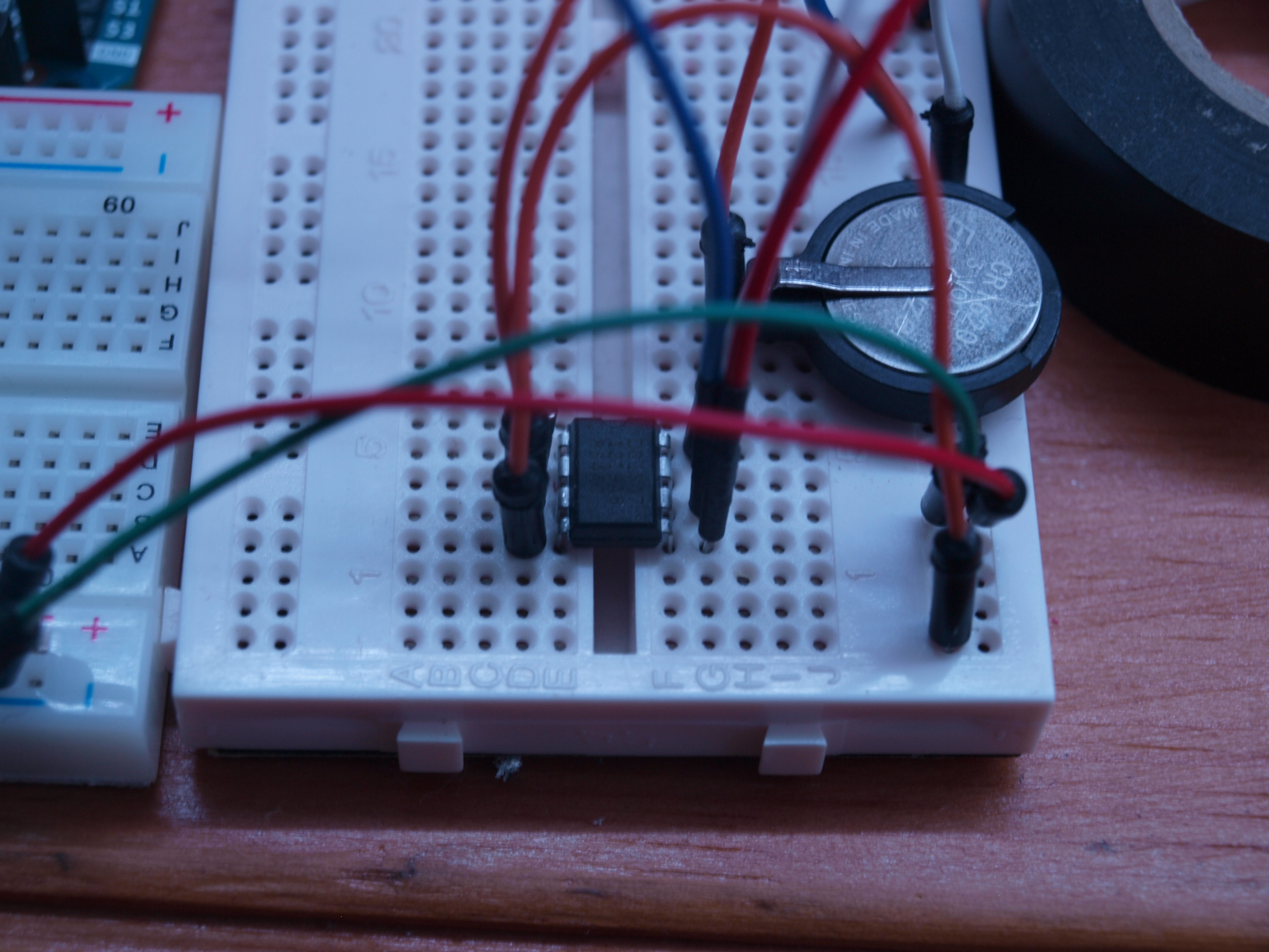
I also used a DS1307+ chip, to keep the time, with a 32.768KhZ watch crystal and a simple 3V coin cell to keep it running when off. I used a really useful library called RTCDue to interface this chip with my Arduino Due, though I plan on eventually running it on an ATMega328PU, in which case I will use this DS1307+ library from Adafruit.
And finally I used the Arduino Due to run the show. My code is available on gitHub so take a look if you are looking to interface with the MAX6921 chip! The library I use is specifically for the arduino Due, but if you change that the code should work perfectly on any other arduino!
Hello; what is the modification in the code to use with Arduino Uno? Thanks
Just for correct – PCB is prepared for MAX6921AUI not AWI – AWI is bigger and does not fit…
Hi Ludek!
Thanks for pointing this out, I’ll change it now. Sorry for any inconvenience caused!
Tom
HI,
Thanks for the brilliant right-up.
Would it be possible to have a wiring diagram of how you connected all 4 models together? I went ahead and purchased the components required, I now just need to figure out how they all go together.
Cheers!
Moein
Hi Meoin!
I have done a quick schematic for you, hope it all goes well. If anything is unclear (Or you want to update me on how it’s going! I’d love to hear!) just respond on here, email me: tom@doayee.co.uk, or tweet me @tomhcousins
Edit: I’ve also added the photo to the gallery at the bottom of this post, if the below photo is unclear!
Cheers very much
A little late, but cheers 😉
Amy chance you can post the code again please? I doesn’t show on your GitHub anymore. Thanks
Hi, the repository is hosted on my personal github, which is why you were struggling to find it. You can see it here. Thanks!