Background
A request from a customer for advice surrounding our BAL (RN52 Development Kit) product, based on the RN52 Bluetooth Adapter from Microchip, wanting to use the product for streaming audio from a microphone to a separate Bluetooth master recording device using the HFP protocol led to more headaches than we could have expected.
The Microchip data sheet didn't provide us with much help, other than to confirm that our electret microphone (found here and bought here should you want to try this yourself) was within the recommended specification. We looked to this article by sixerdoodle (whom we have to thank for setting us off in the correct direction) and tried to build a circuit for our microphone connection.

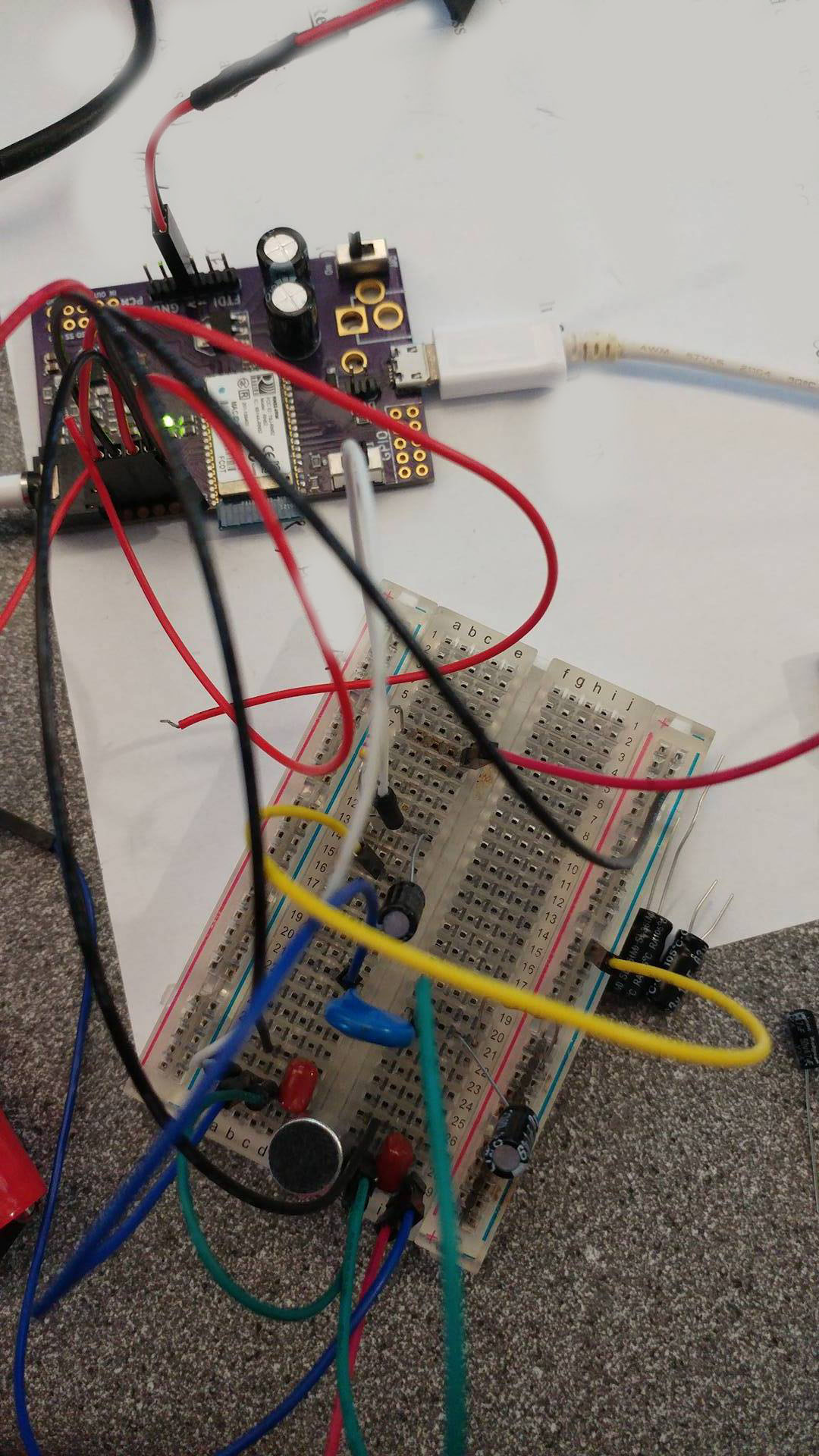
Argh!
Gaaaah! No luck. Excuse the mess in the photo, we were hoping for a quick fix, not something we'd have to write about. We found, similar to the blog linked above, that the MIC would sometimes work on the first call, and after that either be ridiculously quiet, or not work at all. Unideal for a customer to have to turn it on and off every time they start recording.
Then it stopped working altogether, even on first power up.
The MIC_BIAS pin was not producing anywhere near enough voltage or power, it was (very inconsistently) producing 1.4V open circuit and dropping to 0.5V when in use. Not enough for a 3V mic.
Back to the drawing board
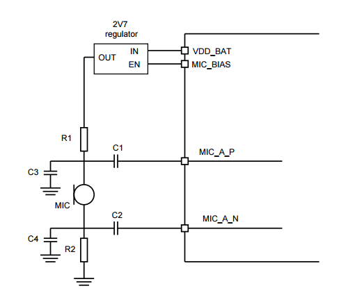
The RN52 is based on a CSR BlueCore5 chip similar to this one. Now the CSR chip is much more advanced than the RN52 as Microchip chose not to implement all of its features. We read here that the MIC_BIAS pin derives its power from BAT_P, a pin used by CSR as part of a battery charging circuit for bluetooth products. This is not a feature which Microchip has implemented in any capacity, and so we put our voltage level issues down to this. We found the circuit shown in one of their datasheets, suggesting the MIC_BIAS was to be used as an enable pin for a regulator to provide power from the mysterious BAT_P pin. We couldnt get our MIC_BIAS to drive anything... a Darlington pair, an L.E.D, nothing.

Resolution
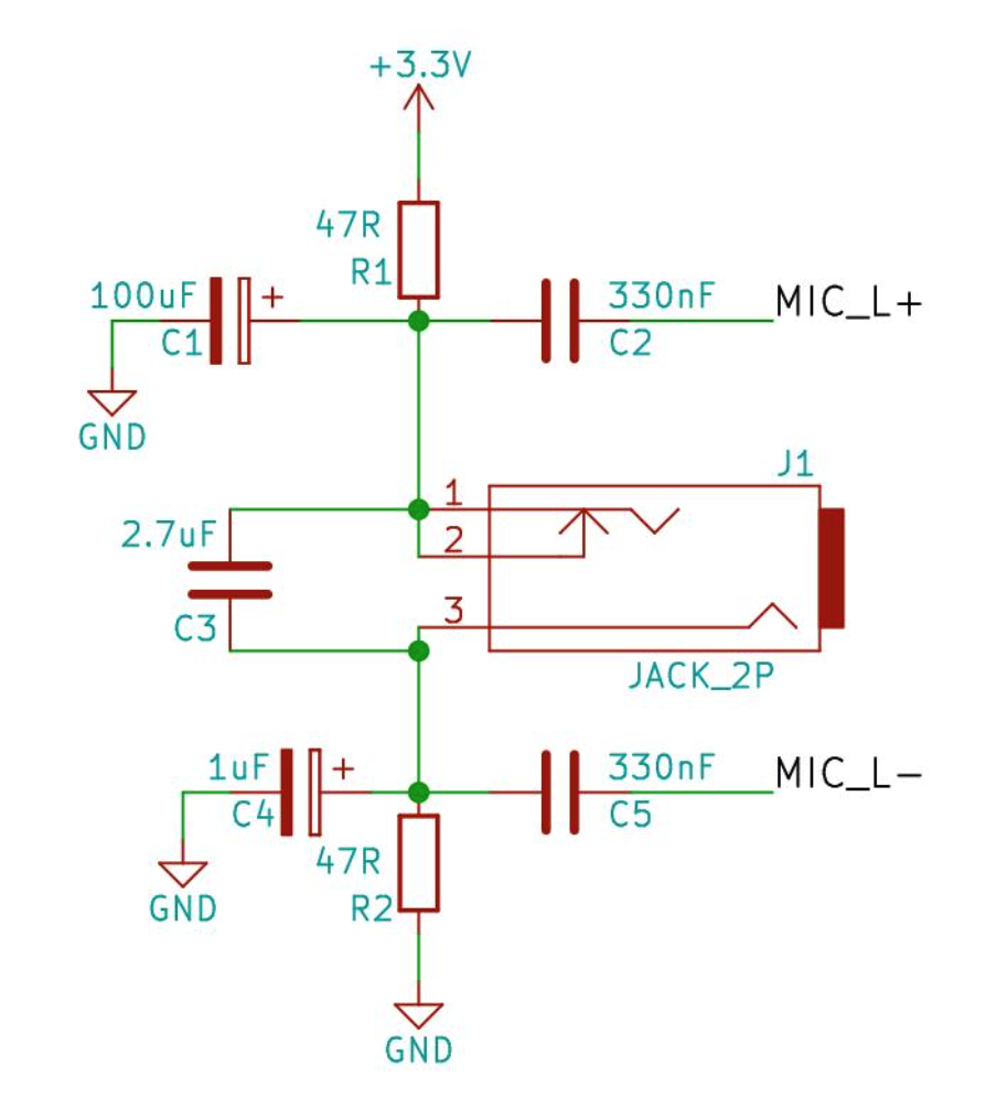
We took a 3.3V rail from elsewhere on our project board and tried to implement the circuit like above that with the RC values shown on the datasheet with the diagram. Still, the voltage drop across the microphone was not high enough. Significant playing around, and the addition of a capacitor across the mic finally yielded what we had worked two days to achieve. A phone call where we could actually converse!
See to the left our final design, which now works just fine! C1 (100uF) is a capacitor that removed the background hum on the input, and by increasing that, it removes it gradually. If the 100uF doesnt work for you try change it to 220uF and it should remove the issue.
A lot of effort for a mono phone call, no?

