
Hey there everyone!
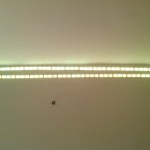
So in part one I dealt with getting the strip hooked up to the MOSFETs and getting it fading through the colour Spectrum!
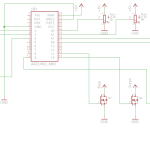
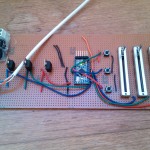
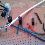
Now that is great and all, but I want to do MUCH more than that. My original plan was to have a controller module with some potentiometers and buttons, so that’s exactly what it’s going to have. I decided to build it all up on vero-board because it’s easy to prototype on vero, but you can use whatever you like! The schematic will be down below.
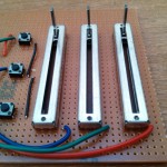
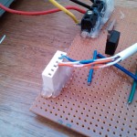
So I first hooked up my slide potentiometers, with pin 1 going to power, pin 3 going to ground, and pin 2 feeding into one of the analog pins on the Arduino Pro Mini (from Sparkfun, you should check them out!), I used pins A1, A2, and A3 for this, but you can use whichever you like. I then hooked up my buttons, with one half of the button going to ground, and one half going into some of the digital I/O pins on the Arduino (yet another brilliant OSHW company). I used pins 2, 3, and 4. I connected them to ground because in the code I will enable something called the internal pull-up resistors for those pins.
Pull-up and pull-down resistors prevent electro-magnetic waves in the air from inducing current in the wires and tricking the micro-controller into thinking the button has been pushed. A pull-down resistor is a large resistor value (usually 10K) that connect the pin to ground, so when any current is induced it goes straight to ground. However when you push the switch all but a little (because of the high resistor value) goes into the micro and registers as a logic high. A pull-up resistor works much the same but reversed, the resistor always connects the pin to positive voltage registering as a logic high, until you push the switch and connect it to ground, thus giving it a logic low. Seen as the Arduino Pro Mini has internal pull-up resistors I am using these so as to minimise the amount of external components I need.
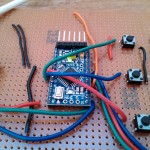
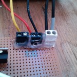
I finally soldered in the MOSFETs according to my circuit diagram, and then added some terminal blocks for the connections to power and some headers for the connections to the strip. I added these in to make sure I could take it out once I had finished it, so I could hack it later on and update code and such.
The audio connection I made by getting a simple 3.5mm Jack cable and cutting the ends off, I stripped the two wires at each end and put one to the input, and one to the output of one of my speakers. I then attached the output one to ground on the controller and the input one to the Arduino. It works okay but at some point I might put in a low pass filter to get just the bass track, which will be easier for the system to react to.
Check out the photos below!
Tom Cousins
P.s. If you don’t know Jeremy Blum (who just got a job at Google – well done!!), check out his blog, and his youtube. He was pretty much my inspiration for starting this, so I thought I’d give him a mention!
P.p.s I got the inspiration for this project from one of the projects Adafruit (a really great company doing some really cool stuff!!!) have done. Check that out if you want to!! The link is here.