
This guide is for the version 1 library and has been replaced by a new library. PLEASE DO NOT USE IT FOR NEW CODE DESIGNS. For the new library, see here.
This command guide is to support the Nixie Tube Driver, from Doayee. The library was written by Thomas Cousins and includes an adaptation of the TimerOne library by Jesse Tane and collaborators. The library falls under the GNU Lesser General Public License and as such is free to use, adapt, redistribute, hack, stick on a billboard, complain about, or contribute to. For any help or queries please email: thom @ doayee dot co dot uk

Hardware
Software
#include - including the library
nixie Nixie() - declaring an instance of the library
Clock Mode CommandssetClockMode() - enabling or disabling the clock mode
setTime() - setting the time
setHours() - setting the hours
setMinutes() - setting the minutes
setSeconds() - setting the seconds
updateTime() - updating the display to the current time
Backlight Colour CyclingsetFade() - start a colour cycle fade
stopFade() - stop a colour cycle fade
display() - displaying a number
setDecimalPoint() - controlling an individual decimal point
blank()- blanking the display
Symbol CommandssetSegment() - setup a segment as a different tube type
setSymbol() - display a symbol
Backlight Commandsbacklight rgb() - declare an instance of the library
setColour() - display a colour
crossFade() - fade between two colours
fadeIn() - fade in to a colour
fadeOut() - fade out to black
Wiring Guide
To properly drive the Nixie Tube Driver, connect the header as below (from the top of the header downwards):
Ground
If your circuit has both analogue and digital ground, connect to the digital ground to avoid adding switching noise to the analogue ground.
GND - Circuit Ground.
Tube control lines
These are all 5V logic connections, with a max switching frequency of 8.0MHz
SRB - Strobe output. Connect to micro-controller for strobe control (strobe turns all elements of all tubes on the driver ON), or leave unconnected.
OE - Output Enable. Connect to micro-controller for blanking features, or tie to +5V (with a max resistance of 1k) if unused.
CLK - Clock. Connect to micro-controller.
DIN - Data In. Connect to micro-controller.
RGB control lines
Note: The RGB cathodes will not function correctly with the library on all pins. Refer to the list below for which pins are safe to use.
Arduino Uno/Micro/Pro/Pro Mini/Nano:
(Or any other ATMega328/ATMega32u4 based Arduino)
Pin 3, Pin 5, Pin 6, Pin 11
Arduino Mega:
(Or any other ATMega2560 based Arduino)
Pin 2, Pin 3, Pin 4, Pin 5, Pin 6, Pin 7, Pin 8, Pin 9, Pin 10, Pin 13, Pin 44, Pin 45, Pin 46
These are all RGB cathodes, to vary the intensity of a colour a PWM signal should be applied to these lines. The lower the value of the duty cycle, the brighter the LED of that colour.
LED Brightness (%) = 100 - Duty Cycle(%)
B - Blue cathode.
G - Green cathode.
R - Red Cathode.
Power Supplies
HV - High Voltage Input. Connect to nixie tube power supply.
+5V - 5V Supply input.
DO NOT touch or alter the connections to your driver when it is powered or has recently been powered. HIGH VOLTAGE CAN KILL.
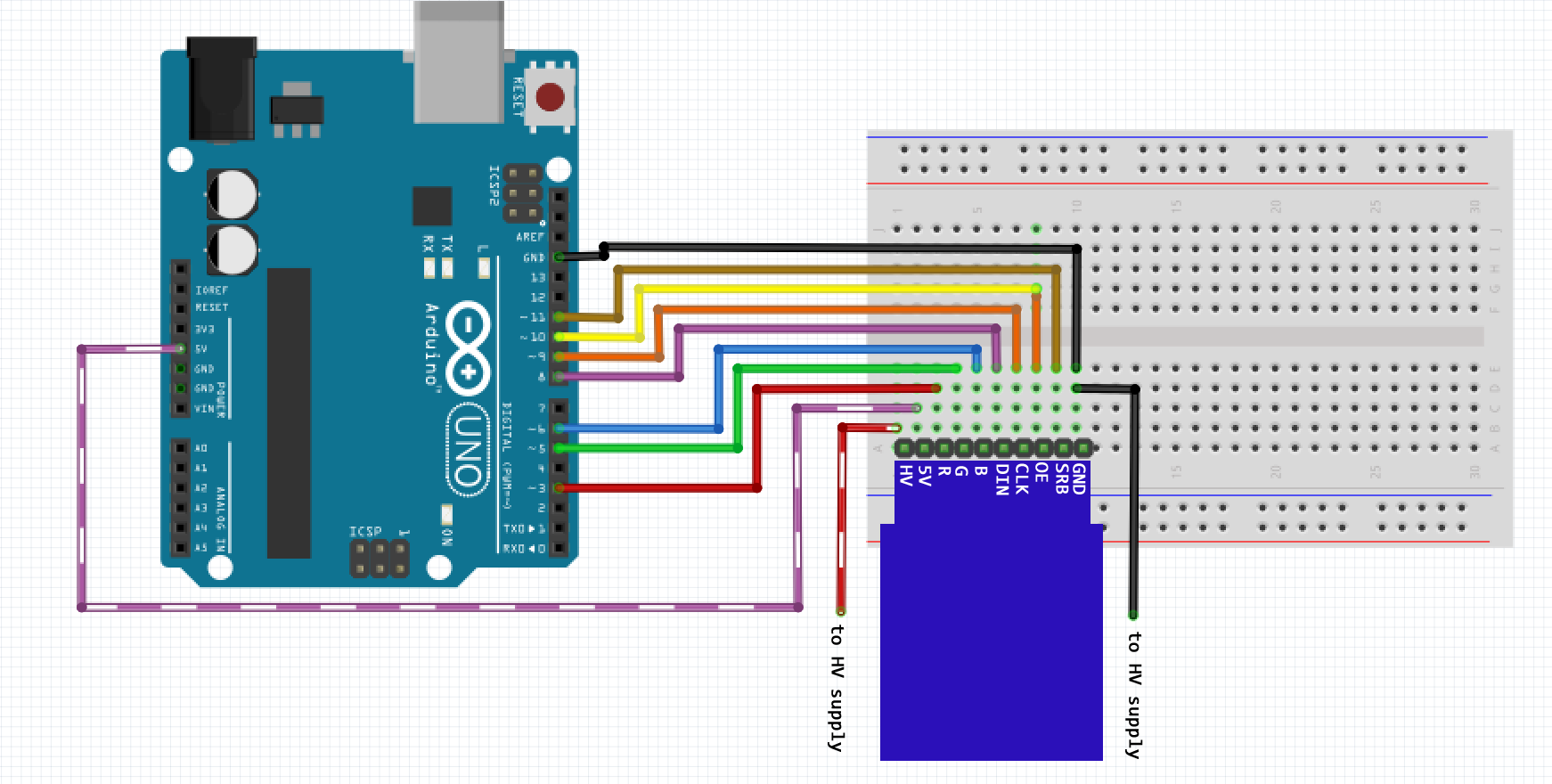
Example hookup to Arduino UNO
Electrical Characteristics
Below are the electrical characteristics for the Nixie Tube Driver, product may not work as specified outside of these regions.
Symbol
VDD
HV
I(Gnd)
Temp
P(Diss)
f(Clk)
t(w)
t(su)
t(h)
t(on)
t(dhl)
t(dlh)
Parameter
Digital supply voltage
High voltage supply
Ground current
Operating temperature
Power dissipation
Clock Frequency
Clock width - high or low
Data setup time after clock falls
Data hold time after clock falls
Turn-on time from strobe
Data output delay after H to L clk
Data output delay after L to H clk
Minimum Value
4.5
Tube Dependent
-
-40
-
-
62
25
10
-
-
-
Typical Value
5.0
180
-
-
-
5.0
-
-
-
-
-
-
Maximum Value
15.0
250
1950
85
3850
8.0
-
-
-
500
100
100
Unit
V
V
mA
°C
mW
MHz
ns
ns
ns
ns
ns
ns
Setup
#include <NixieDriver.h>
Whenever you are using the Nixie tube driver library, you must include it at the top of your sketch. This allows the IDE to recognise commands from the library.
#include <NixieDriver.h>
nixie nixie(data, clock, optional: output_enable, optional: strobe);
Parameters:
int data - Pin which the data line is connected to
int clock - Pin which the clock line is connected to
int output_enable - Pin which the output enable line is connected to (OPTIONAL)
int strobe - Pin which the strobe line is connected to (OPTIONAL)
To begin using the library you must first define the class, in this case, ‘nixie’, but you could call it anything. The pins you are connecting to the Nixie tube driver with must be specified in the data and clock fields. The output_enable and strobe fields are optional connections, but we recommend connecting them to access the full functionality of the library.
//Pin assignments
const int data = 8;
const int clock = 9;
const int oe = 10;

//Create instances of class - Strobe not used
nixie nixie(data, clock, oe);

/* * * * OR * * * */

//Create instance of class with custom name - Strobe and OE not used
nixie myName(data, clock);
From now on all commands must start with your class name, then a dot. This links the command to the library, and without it the sketch will not be able to compile.
General Commands
display(numberToDisplay);
Parameters:
float / int / long numberToDisplay - The number you wish to display
Returns:
None
The display function is the most useful function of the library; it takes an input number, which takes an integer, a long integer, or a floating point number (see https://www.arduino.cc/en/Reference/HomePage for info on data types) and displays it on the tubes. For a floating point number, the decimal point position is calculated and implemented automatically, though this will require IN12B tubes to display.
float numberToDisplay = 3.14159;
nixie.display(numberToDisplay);    //Displays pi on the tubes
setDecimalPoint(segment, state);
Parameters:
int segment - The segment of the decimal point you wish to alter (indexed from 0)
boolean state - The state of the decimal point
Returns:
None
Should you wish to control the decimal point yourself, this command allows you to manually turn on or off the decimal points. Note: Segments are indexed from 0 (i.e. the first digit is segment 0, the second segment 1 etc.)
nixie.setDecimalPoint(3, 1); //Turns on the 3rd segment decimal point
blank(state);
Parameters:
boolean state - TRUE for blank, FALSE for not blanked
Returns:
None
nixie.blank(1);    //Blanks the display
nixie.blank(0);    //Unblanks the display
Clock Mode Commands
Clock mode is a convenient mode included with the library, which allows the display to be used quickly and easily as a clock or timer. The tubes will display all numbers in 3 groups of two, as shown: HH.MM.SS with a decimal point between each group.
setClockMode(state);
Parameters:
boolean state - TRUE for clock mode enabled, FALSE for clock mode disabled
Returns:
None
nixie.setClockMode(1);    //Enables clock mode.
nixie.setClockMode(0);    //Disables clock mode.
The following commands only function when clock mode is enabled:
setTime(hours, minutes, seconds);
Parameters:
int hours - The hours to set
int minutes - The minutes to set
int seconds - The seconds to set
Returns:
None
All inputs to this function are in integer form.
nixie.setTime(13, 27, 00); //Sets the time to 27 minutes past 1.
setHours(hours);
Parameters:
int hours - The hours to set
Returns:
None
nixie.setHour(11); //Sets the hours to 11
setMinutes(minutes);
Parameters:
int minutes - The minutes to set
Returns:
None
nixie.setMinutes(23); //Sets the minutes to 23
setSeconds(seconds);
Parameters:
int seconds - The seconds to set
Returns:
None
nixie.setSeconds(58); //Sets the seconds to 58
updateTime();
Parameters:
None
Returns:
boolean - TRUE for successful update, FALSE for error
Updates the time physically displayed on the tubes to the current time held in memory.
nixie.updateTime(); //Updates the time displayed on the tubes
Symbol Commands
These commands allow the user to make use of the IN15A and IN15B tubes, which come with a variety of symbols for the user to implement.
The symbols to the left are available, with their tube type and name specified.
setSegment(segment, segmentType);
Parameters:
int segment - the segment to change the tube type of
int segmentType - the type of segment (IN15A, IN15B or NUMBER), evaluates to an integer
Returns:
None
nixie.setSegment(0, IN15A);
//Sets the first segment to an IN15A tube

nixie.setSegment(5, IN15B);
//Sets the final segment to an IN15B tube

nixie.setSegment(1, NUMBER);
//Sets the 2nd segment to an IN12A/B tube
| Symbol | Name | Tube |
| µ | MU, MICRO | IN15A |
| n | NANO | IN15A |
| % | PERCENT | IN15A |
| π | CAP_PI | IN15A |
| k | KILO, KELVIN | IN15A |
| M | MEGA, METERS, MINUTES | IN15A |
| m | MILLI | IN15A |
| + | PLUS | IN15A |
| - | MINUS | IN15A |
| P | PICO | IN15A |
| W | WATTS | IN15B |
| A | AMPS | IN15B |
| Ω | OHMS | IN15B |
| S | SECONDS, SIEMENS | IN15B |
| V | VOLTS | IN15B |
| H | HENRYS | IN15B |
| Hz | HERTZ | IN15B |
| F | FARADS | IN15B |
| BLANK | IN12A/B, IN15A/B |
setSymbol(segment, symbol);
Parameters:
int segment - the segment to display a symbol on
int symbol - the symbol to display (see table), evaluates to an integer
Returns:
None
nixie.setSymbol(0, MICRO);    //Sets the first segment to display ‘µ’

nixie.setSymbol(5, AMPS);    //Sets the final segment to display ‘A’
Backlight Commands
The nixie library includes a comprehensive backlight controller, which allows smooth blending of colours between fades, custom colour loops, and user controllable durations, all in the background of the sketch. The backlight controller functions as a completely independent sub-library, and therefore requires its own initialisation.
backlight rgb(redPin, greenPin, bluePin);
Parameters:
int redPin - the Arduino pin which the red line is connected to
int greenPin - the Arduino pin which the green line is connected to
int bluePin - the Arduino pin which the blue line is connected to
//Pin assignments for backlight pins
const int redPin = 3;
const int greenPin = 5;
const int bluePin = 6;

//Create instance of background class
backlight rgb(redPin, greenPin, bluePin);
To begin using the backlight controller you must first define a separate class, in this case, ‘rgb’, but you could call it anything. The pins you are connecting to the backlight LEDs with must be specified in the redPin, greenPin and bluePin segments.
setColour(colour);
Parameters:
int colour[] - a 3 element array detailing the colour, in {R,G,B} format. The elements can have values from 0-255
Returns:
None
This function changes the colour of the backlight to whatever colour is specified, in the example it is yellow.
rgb.setColour(rgb.yellow); //Sets the backlight to display yellow
You can use one of our included colours, specified in the list below, or input your own colour using this format:
int myColour[3] = {red, green, blue}
int myColour[3] = {100, 40, 255};
rgb.setColour(myColour);
Amounts of each colour can vary from 0 to 255.
To use the colours included with the library already, simply write the name of a colour, preceded by your library object name (in our case 'rgb').
Included colours:
- white
- red
- green
- blue
- yellow
- dimWhite
- magenta
- aqua
- purple
crossFade(startColour, endColour, duration);
Parameters:
int startColour[] - a 3 element array detailing the start colour
int endColour[] - a 3 element array detailing the end colour
int duration - the duration in which the fade should take place
Returns:
None
This function allows seamless blending of two colours, over a specified time. The colours must be predefined, or part of our included set.
rgb.crossFade(rgb.red, rgb.blue, 1000); //Fade from red to blue with a duration of 1s.
fadeIn(colour, duration);
Parameters:
int colour[] - a 3 element array detailing the colour to fade in to
int duration - the duration in which the fade should take place
Returns:
None
This function fades a colour in from black over a specified time period.
rgb.fadeIn(rgb.aqua, 3000); //Fade in to aqua over 3s.
fadeout(duration);
Parameters:
int duration - the duration in which the fade out should happen
Returns:
None
This function fades a colour out to black over a specified time period.
rgb.fadeOut(500); //Fade out over half a second.
Background Colour Cycling
The library has features that allow you to set up a colour fade, and start it cycling in the background of your code.
To do this you need to set up the colour cycle first, before you begin the fade.
Setting up a colour cycle:
The following format applies for setting up a cycle. First, you must make an integer array, of dimension ‘CYCLETYPE’; this is a custom definition to the library. You can then specify colours and their respective durations (note: this is the duration of the fade from one colour to the next, it will not remain on the specified colour for that time. Should you wish to remain on a single colour for a period of time you should put 2 of the same colour sequentially).
There can be a maximum of 16 colours in a colour cycle, before the ENDCYCLE.
int colourCycle[CYCLETYPE] = {
{COLOUR1, Duration},
{COLOUR2, Duration},
{…},
{COLOURN, Duration},
{ENDCYCLE}
};
For example:
int cycle1[CYCLETYPE] = {
    { RED,     1000 },    //Fade from red to yellow in 1s
    { YELLOW,  4000 },    //Fade from yellow to green in 4s
    { GREEN,   5000 },    //Fade from green to blue in 5s
    { BLUE,    8000 },    //Fade from blue to pink in 8s
    { MAGENTA, 1000 },    //Fade from pink to red in 1s
    { ENDCYCLE      }
};
The colours must be specified in capitals from the following list:
- BLACK
- WHITE
- RED
- GREEN
- BLUE
- YELLOW
- DIMWHITE
- AQUA
- MAGENTA
- PURPLE
Should you wish to specify your own colours you should do so using a definition, rather than a variable. This should be done at the top of your code, after #include <NixieDriver.h>. This does not need a type and this line should not end with a semi-colon.
#define MYCOLOUR 100, 40, 255
Starting/Stopping your colour cycle:
setFade(colourCycle);
Parameters:
int colourCycle[CYCLETYPE] - the colour cycle you wish to begin
Returns:
None
This will begin fading through the cycle specified in the background of the code.
rgb.setFade(cycle1); //Start fading cycle1
stopFade(duration);
Parameters:
int duration - the duration in which you wish the colour cycle to stop cycling and fade out
Returns:
None
This will stop the cycle wherever it currently is and fade it to black over the time period specified.
rgb.stopFade(3000); //Stops the cycle and fades out over 3s.